21 Unique Bcd Counter Circuit Diagram
Bcd Counter Circuit Diagram edutek ltd uk CBricks Pages Counter BCD htmlThis circuit will count input pulses and generate a binary value from 0 to 9 on its outputs BCD Binary Coded Decimal Counts from 0 to 9 and then repeats Simple to use two counters pers IC Bcd Counter Circuit Diagram counterbcd counterBCD or Decade Counter Circuit A binary coded decimal BCD is a serial digital counter that counts ten digits And it resets for every new clock input As it can go through 10 unique combinations of output it is also called as Decade counter
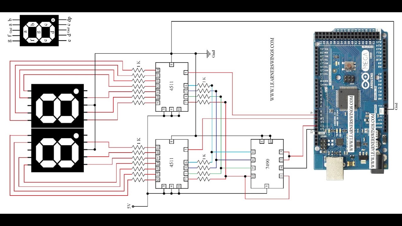
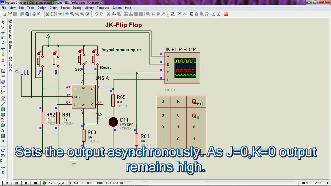
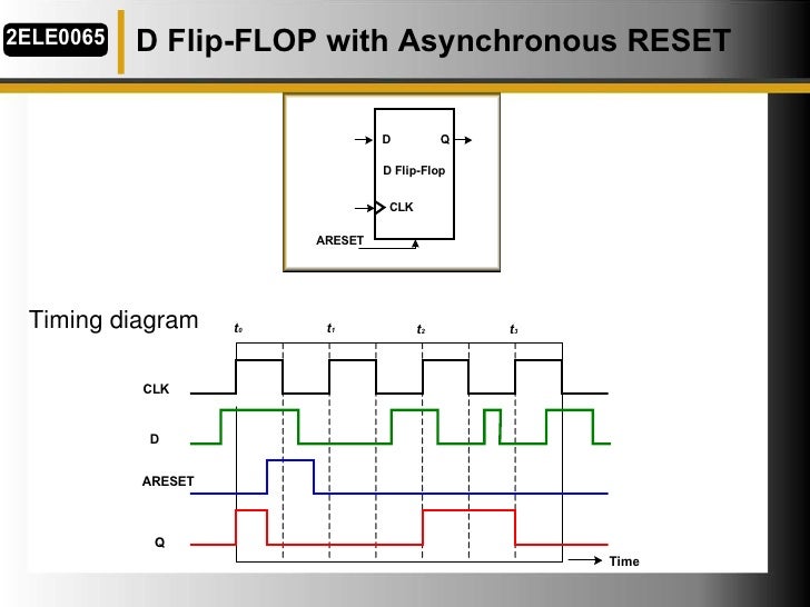
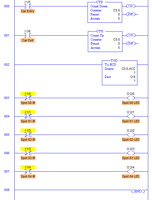
7 segment led display decoder Here is the circuit diagram of display decoder which is used to convert a BCD or binary code into a 7 segment code used to operate a 7 segment LED display BCD to 7 Segment LED Display Decoder Circuit July 6 2015 By Administrator 32 Comments Table of Contents This circuit can be modified using timers and counters to Bcd Counter Circuit Diagram allaboutcircuits Worksheets Digital CircuitsComplete a timing diagram for this circuit and determine its direction of count and also whether it is a synchronous counter or an asynchronous counter Reveal answer Hide answer This is an asynchronous up counter edutek ltd uk Tutorial Pages BCD Counter 4510 htmlThe 4510 is a 4 bit SYNCHRONOUS BCD Binary Coded Decimal counter which means all the outputs change at the same time as opposed to a RIPPLE BINARY counter whose outputs changed sequentially albeit very quickly
DIAGRAM Counter Circuit The counter chain consists of two dual BCD up counters IC2 and IC3 The clock inputs of all the counters are grounded The cascading of counters can be done by connecting D output of the previous stage to the enable input pin 10 of the next stage of counters keeping clock input of the latter at Bcd Counter Circuit Diagram edutek ltd uk Tutorial Pages BCD Counter 4510 htmlThe 4510 is a 4 bit SYNCHRONOUS BCD Binary Coded Decimal counter which means all the outputs change at the same time as opposed to a RIPPLE BINARY counter whose outputs changed sequentially albeit very quickly allaboutcircuits Sequential CircuitsIf the Up Down control line is made low the bottom AND gates become enabled and the circuit functions identically to the second down counter circuit shown in this section To illustrate here is a diagram showing the circuit in the up counting mode all disabled circuitry shown in grey rather than black
Bcd Counter Circuit Diagram Gallery
imsadg3, image source: digsys.upc.es

maxresdefault, image source: www.youtube.com
7 segment counter circuit ic cd4026, image source: www.gadgetronicx.com

working with seven segment displays fig11, image source: www.jameco.com

4510_02, image source: redy.3x.ro

mini project rom based sine wave generator 8 728, image source: elsalvadorla.org
maxresdefault, image source: www.youtube.com

segment4, image source: www.electronics-tutorials.ws
proxy, image source: forum.allaboutcircuits.com
plc program car parking system 02, image source: www.sanfoundry.com
th?id=OGC, image source: www.iamtechnical.com


block diagram of LED Temperature1, image source: electronicsproject.org
Arduino 7 Segment Circuit, image source: circuitdigest.com


residual current device, image source: www.iamtechnical.com

7 Segment Display Arduino Circuit, image source: circuits4you.com
PIC16F84A using seven segment display schematic, image source: pic-microcontroller.com


maxresdefault, image source: www.youtube.com
direct coupling, image source: www.iamtechnical.com


7447 pin configuration, image source: www.electroschematics.com
700px Xilinx4BitAdderTimingDiagram, image source: cs.smith.edu


Comments
Post a Comment