21 Unique Ammonia Refrigeration Cycle Diagram
Ammonia Refrigeration Cycle Diagram is a process of removing heat from a low temperature reservoir and transferring it to a high temperature reservoir The work of heat transfer is traditionally driven by mechanical means but can also be driven by heat magnetism electricity laser or other means Refrigeration has many applications including but not limited to household refrigerators industrial freezers Ammonia Refrigeration Cycle Diagram rses assets serviceapplicationmanual 620 89s pdfAmmonia as the base for nitric acid is an important building block in the manufacture of many chemical compounds such as cleaning fluids catalysts used in the manufacture of plastics and process
lpappliances g absorp htmlPROPANE REFRIGERATION UNITS How do they work Here is the technical data on how gas or heating element driven absorption systems cool your LP fridge or freezer Ammonia Refrigeration Cycle Diagram ammoniatrainingsolutions za courses 1 Ammonia Plant For SAQCCGas Category A Ammonia Plant Training Part 1 A two day course incorporating the operation of basic ammonia refrigeration systems and ignou ac in upload Unit 2 32 pdf18 Refrigeration and Air Conditioning The vapour compression cycle which is used in vapour compression refrigeration system is now a days used for all purpose refrigeration
americanaquariumproducts Nitrogen Cycle htmlBy Carl Strohmeyer Updated 4 10 18 INTRODUCTION Please click on the picture for a better view of a BASIC explanation of the Aquarium Nitrogen Cycle Please see a more advanced diagram Ammonia Refrigeration Cycle Diagram ignou ac in upload Unit 2 32 pdf18 Refrigeration and Air Conditioning The vapour compression cycle which is used in vapour compression refrigeration system is now a days used for all purpose refrigeration absorptionchiller4u blogspot 2013 02 ammoniawater absorption Feb 02 2013 In the absorption refrigerating system the compressor is replaced with an absorber generator and pump Figure 6 7 shows the schematic diagram of a vapor absorption refrigeration
Ammonia Refrigeration Cycle Diagram Gallery
hw9 sp11 WB4, image source: www.learnthermo.com

refrigeration, image source: www.mechlectures.com

248a8165994b85ac900ff2cacfa27581, image source: www.pinterest.com

maxresdefault, image source: www.youtube.com
cycle4, image source: www.neilorme.com
62871 004 2FC91A5F, image source: refrigerationbest.blogspot.com
th?id=OGC, image source: berg-group.com

maxresdefault, image source: www.youtube.com
refrigeration_cycle, image source: gasairsystems.com

Spiral plate heat exchangers adsorption chiller for air conditioning system, image source: www.researchgate.net

RefrigerationSystem, image source: refrigerationnew.blogspot.com

hqdefault, image source: www.youtube.com
10 5+Schmatic+and+T s+Diagram+for+Actual+Vapor Compression+Refrigeration+Cycle+%28Fig, image source: slideplayer.com
HVAC_schematic, image source: refrigerationnew.blogspot.com
42, image source: goldman.com.au

113484, image source: www.achrnews.com

maxresdefault, image source: www.youtube.com

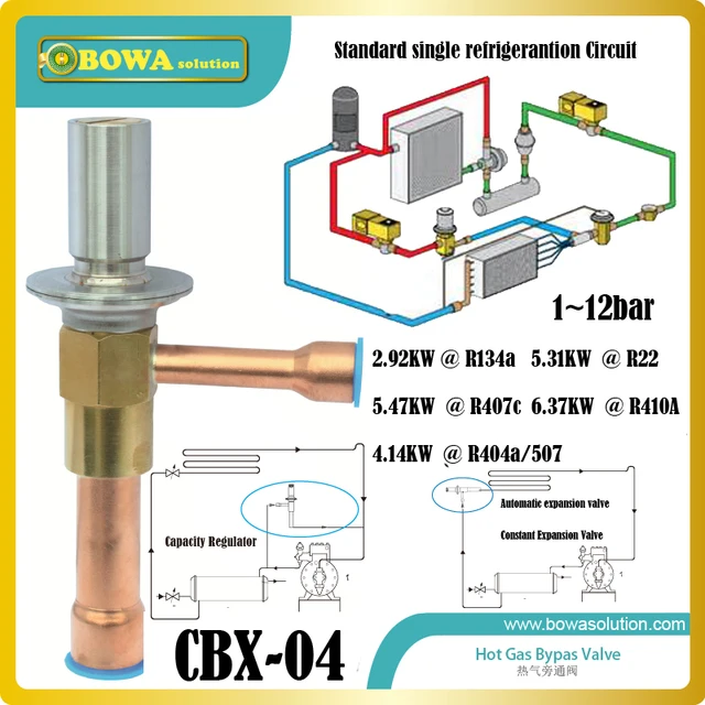
CBX 04 R410A pressure regulator connecting compressor discharge line and suction line to balance system pressure, image source: www.aliexpress.com
refrigerator current relay circuit, image source: www.refrigeratordiagrams.com

08, image source: ienergyguru.com
Comments
Post a Comment