21 Fresh Comparator Logic Diagram
Comparator Logic Diagram edsim51 simInstructions htmlSyntax Highlighting Now assembly code written in EdSim51 is automatically syntax highlighted Instructions are coloured blue assembler directives such as ORG USING etc are coloured purple aliases for example the assembler replaces TMOD with the address of TMOD are coloured orange and comments are coloured green Comparator Logic Diagram ermicro blog p 1578Comment by pichaha Hi currently I am using LM324 comparator to supply digital logic signal from IR sensor to my mcu according to the principle of comparator when the inverting input is greater than the non inverting input the output of the comparator will be low and vice versa but the results that I obtianed is not really precise
interfacebus Glossary of Terms M htmlThe Masking circuit above uses a predefined mask word to change the incoming Data into an output that depends both on the incoming data and the stored mask Comparator Logic Diagram ti lit ds symlink lm392 n pdfLM392 N ti SNOSBT5D APRIL 1998 REVISED MARCH 2013 lm392 NLow Power Operational Amplifier Voltage Comparator Check for Samples LM392 N onsemi pub Collateral LM393 D PDFLM393 LM393E LM293 LM2903 LM2903E LM2903V NCV2903 onsemi 2 MAXIMUM RATINGS Rating Symbol Value Unit Power Supply Voltage VCC 36 or 18 V Input Differential Voltage VIDR 36 V Input Common Mode Voltage Range VICR 0 3 to 36 V Output Voltage VO 36 V Output Short Circuit to Ground
ti lit ds symlink lm319 n pdftechnical documents tools software support community Comparator Logic Diagram onsemi pub Collateral LM393 D PDFLM393 LM393E LM293 LM2903 LM2903E LM2903V NCV2903 onsemi 2 MAXIMUM RATINGS Rating Symbol Value Unit Power Supply Voltage VCC 36 or 18 V Input Differential Voltage VIDR 36 V Input Common Mode Voltage Range VICR 0 3 to 36 V Output Voltage VO 36 V Output Short Circuit to Ground electronics tutorials ws Operational AmplifiersThe Op amp comparator compares one analogue voltage level with another analogue voltage level or some preset reference voltage V REF and produces an output signal based on this voltage comparison In other words the op amp voltage comparator compares the magnitudes of two voltage inputs and determines which is the largest of the two
Comparator Logic Diagram Gallery
lcd tv power supply circuit diagram juanribon com samsung cl29x50design led lamp driver images of dia_led circuit diagrams_telephone ringer circuit scr switch lm324 comparator, image source: farhek.com

lcd tv power supply circuit diagram juanribon com samsung cl29x50design led lamp driver images of dia_led circuit diagrams_telephone ringer circuit scr switch lm324 comparator _1100x1052, image source: farhek.com

logic probe with sound circuit diagram 2, image source: www.learningelectronics.net

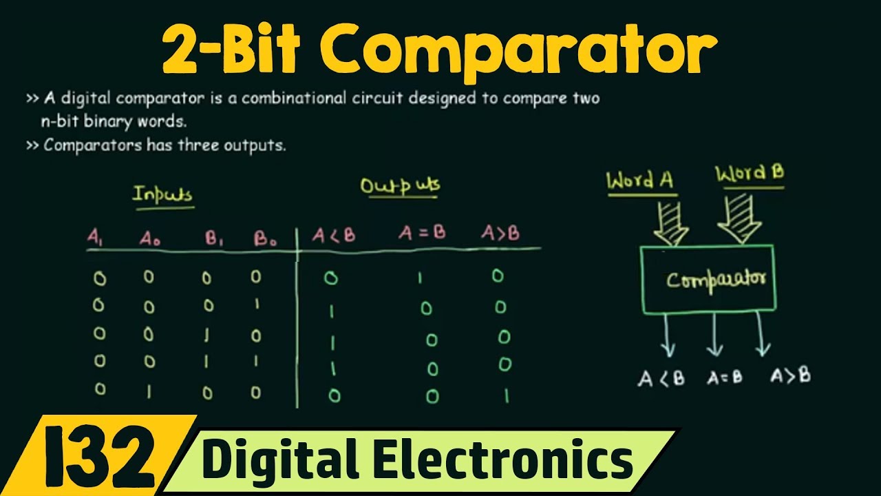
maxresdefault, image source: www.youtube.com
Dj6XM, image source: electronics.stackexchange.com

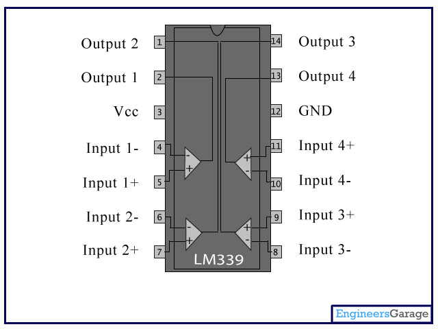
LM339_1, image source: www.engineersgarage.com
![]()
design and construction of automatic dualaxis solar tracking system using light dependent resistor ldr sensors 6 638, image source: www.slideshare.net
3YLXy, image source: electronics.stackexchange.com

21, image source: engineersworld.wordpress.com
patent us5831562 differential sample and hold circuit with drawing_sample and hold circuit_high impedance circuit transistor led 9v dc power supply lm358 comparator fire alarm, image source: farhek.com

Laser Security Circuit, image source: circuitdigest.com

xbe7E, image source: electronics.stackexchange.com
8d055e349eb61ca6ea760f69ecc877764bcc06a9_large, image source: www.brighthubengineering.com

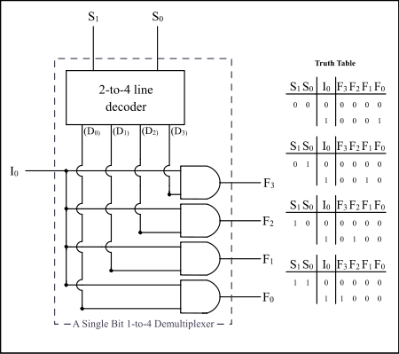
450px Demultiplexer_Example01, image source: en.wikipedia.org
sensors 13 03157f3 1024, image source: www.mdpi.com

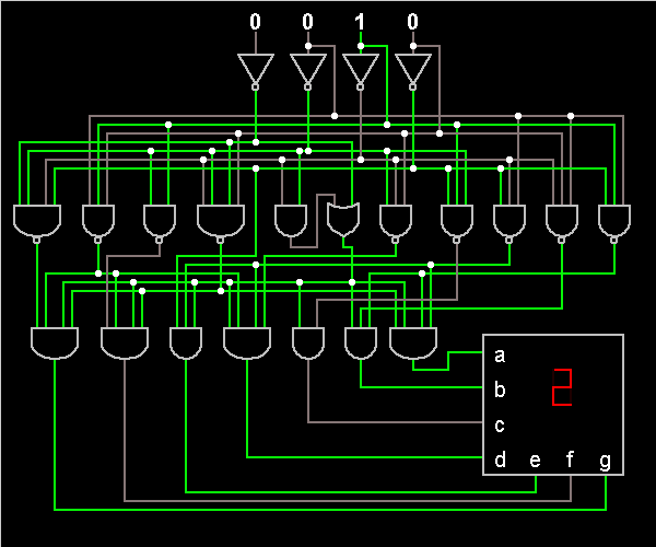
7 segment led decoder, image source: www.indiabix.com
4274259_orig, image source: digitalbyte.weebly.com


FRT9JXEHZJOTIRC, image source: www.instructables.com
burglar%20alarm, image source: electronicprojectcircuits.blogspot.com


8x8+dot+matrix+led+pinout 794386, image source: circuitdesolator.blogspot.com


Comments
Post a Comment