21 Best Lm741 Circuit Diagram
Lm741 Circuit Diagram electronicecircuits Electronic Circuits741 Stereo PreAmplifier Circuit Diagram This preamp circuit provides better than 20dB gain in each channel Lm741 Circuit Diagram ti lit ds symlink lm741 pdfLM741 SNOSC25D MAY 1998 REVISED OCTOBER 2015 ti 6 Specifications 6 1 Absolute Maximum Ratings over operating free air temperature range unless otherwise noted 1 2 3 MIN
pdf datasheetcatalog datasheet fairchild LM741 pdfLM741 2 Schematic Diagram Absolute Maximum Ratings TA 25 C Parameter Symbol Value Unit Supply Voltage VCC 18 V Differential Input Voltage VI DIFF 30 V Lm741 Circuit Diagram eleccircuit AmplifiersThis circuit is a mono pre amp circuit which can be used with a variety of inputs Can be applied for extending the phone and the other with When AF IN input signal to pin 3 of IC1 and The voltage input to pin 2 of IC1 The IC number LM741 used to amplifier circuit Output at Pin 6 fire alarm circuitCircuit 1 Simple Fire Alarm Circuit This is a very simple alarm circuit using Thermistor LM358 Operational Amplifier and a Buzzer Circuit Diagram
learningaboutelectronics a LM741 op amp chip to a circuitIn this article we ll explain how to connect a LM741 Op Amp Chip to a circuit to allow for amplification A LM741 Op Amp is a versatile chip that can be made to do a variety of tasks such as a variety of math functions as well as amplification In this lesson we will use it as an amplifier Pin 2 Lm741 Circuit Diagram fire alarm circuitCircuit 1 Simple Fire Alarm Circuit This is a very simple alarm circuit using Thermistor LM358 Operational Amplifier and a Buzzer Circuit Diagram electronicecircuits Electronic CircuitsAutomatic Gain Control PreAmplifier Circuit Diagram The preamp circuit uses an easily obtained 741 op amp set for an internal gain about 200
Lm741 Circuit Diagram Gallery
Fire Alarm Circuit Using lm341, image source: www.electronicshub.org
800px OpAmpTransistorLevel_Colored_Labeled, image source: www.cycfi.com

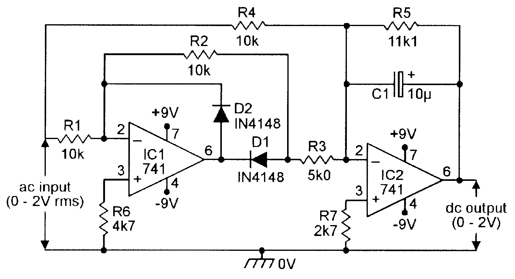
NV_1001_Marston_Figure06, image source: www.nutsvolts.com
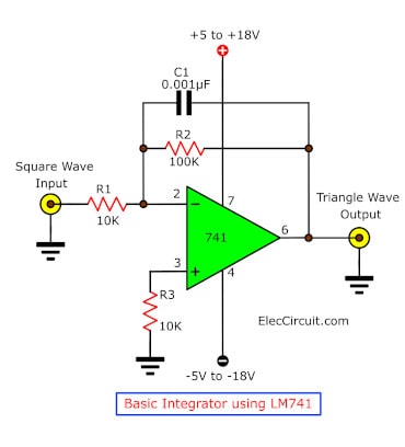
basic integrator by lm741, image source: wiringdiagram.karaharmsphotography.com

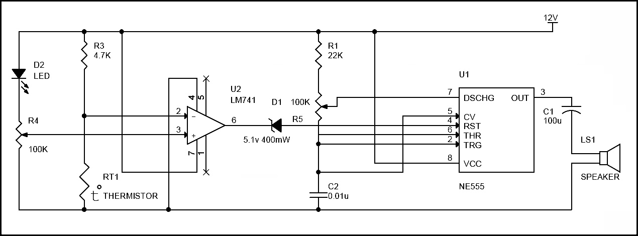
circuit diagram of electronics thermometer, image source: electronicsproject.org
electrosmash mxr microamp analysis the micro amp circuit can be divided into two blocks power supply stage and op amplifier_op amp schematic_dual 2 ohm wiring schematic diagram, image source: farhek.com

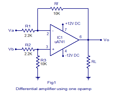
practical differential amplifier circuit, image source: www.circuitstoday.com

fuzz audio converter using lm324, image source: www.circuitdiagramworld.com

776eec3f6fca96a4377eb3e728d3eb840b00ee04, image source: www.bbc.co.uk

comparator_lm358, image source: www.bristolwatch.com

qHwVj, image source: electronics.stackexchange.com
lm339th, image source: www.bristolwatch.com

lm317_tester, image source: www.zen22142.zen.co.uk

Op_Amp_741, image source: reviseomatic.org
741 Opamp Pinout, image source: electrosome.com

1200px 555_Pinout, image source: en.wikipedia.org
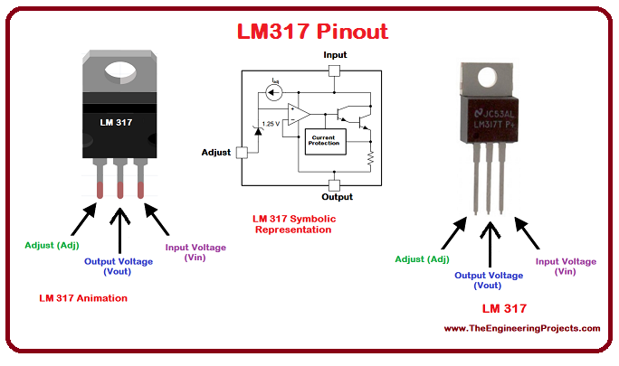
LM317_Pinout, image source: www.theengineeringprojects.com
uA741 pinout, image source: www.circuitstoday.com

UA741 datasheet, image source: www.bingapis.com

dry cell battery charger using lm741 and ic4011, image source: skemarangkaianpcb.com


Comments
Post a Comment