21 Best Basic Refrigeration System Diagram
Basic Refrigeration System Diagram an air conditioning system to operate with economy the refrigerant must be used repeatedly For this reason all air conditioners use the same cycle of compression condensation expansion and evaporation in a closed circuit Performance Testing Compressor Evaporator Part Identification Air Conditioning Basic Refrigeration System Diagram section by section It important to understand the basic refrigeration cycle to comprehend what is going on within the air conditioner units we cannot see it The refrigeration cycle tells us if there is air in the central air conditioner units what to repair after troubleshooting the refrigeration system if there is enough air conditioner freon
group the science behind refrigerationBasic Refrigeration System Fundamentals The Pressure Enthalpy The pressure enthalpy also called pressure heat diagram is used to describe in engineering terms the interaction of heat pressure temperature heat content and cooling capacity of Basic Refrigeration System Diagram Walker Corporate Trainer Hill PHOENIX Compressor Basic Refrigeration Cycle Evaporator Condenser Receiver Expansion Device Vapor Compression Cycle Th MOVEMENT Cooling by the refrigeration system in the condenser as the refrigerant changes liquid to a gas in the evaporator the basic refrigeration cycleMechanical refrigeration is accomplished by continuously circulating evaporating and condensing a fixed supply of refrigerant in a closed system This article describes and illustrates the basics of the refrigeration cycle
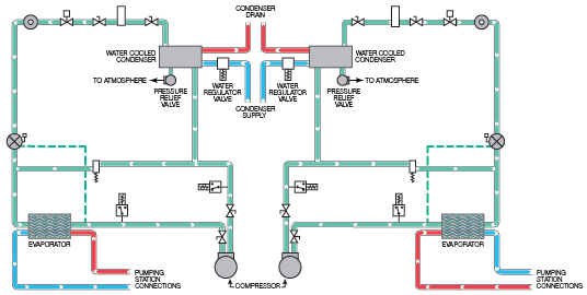
air conditioning and refrigeration guide refrigeration The metering device component 3 on this refrigeration cycle diagram is the dividing point between the high pressure and low pressure sides of the system And is designed to maintain a specific rate of flow of refrigerant into the low side of the system Basic Refrigeration System Diagram the basic refrigeration cycleMechanical refrigeration is accomplished by continuously circulating evaporating and condensing a fixed supply of refrigerant in a closed system This article describes and illustrates the basics of the refrigeration cycle refrigerationbasics RBIII controls1 htmLets add a basic control system to a refrigeration system First we need to know what loads there are to be controlled The image on the left shows a small split system for a walk in cooler with 3 electrical devices a compressor condenser fan motor and evaporator fan motor
Basic Refrigeration System Diagram Gallery
flow, image source: web.mit.edu

ECRefrigSysFig1, image source: www.baltimoreaircoil.com

central chillers flow schematic, image source: www.mokon.com
Vapor Compression Refrigeration Cycle 1, image source: www.araner.com


hvac2, image source: lightfootmechanical.com
Figure+1, image source: jmpcoblog.com

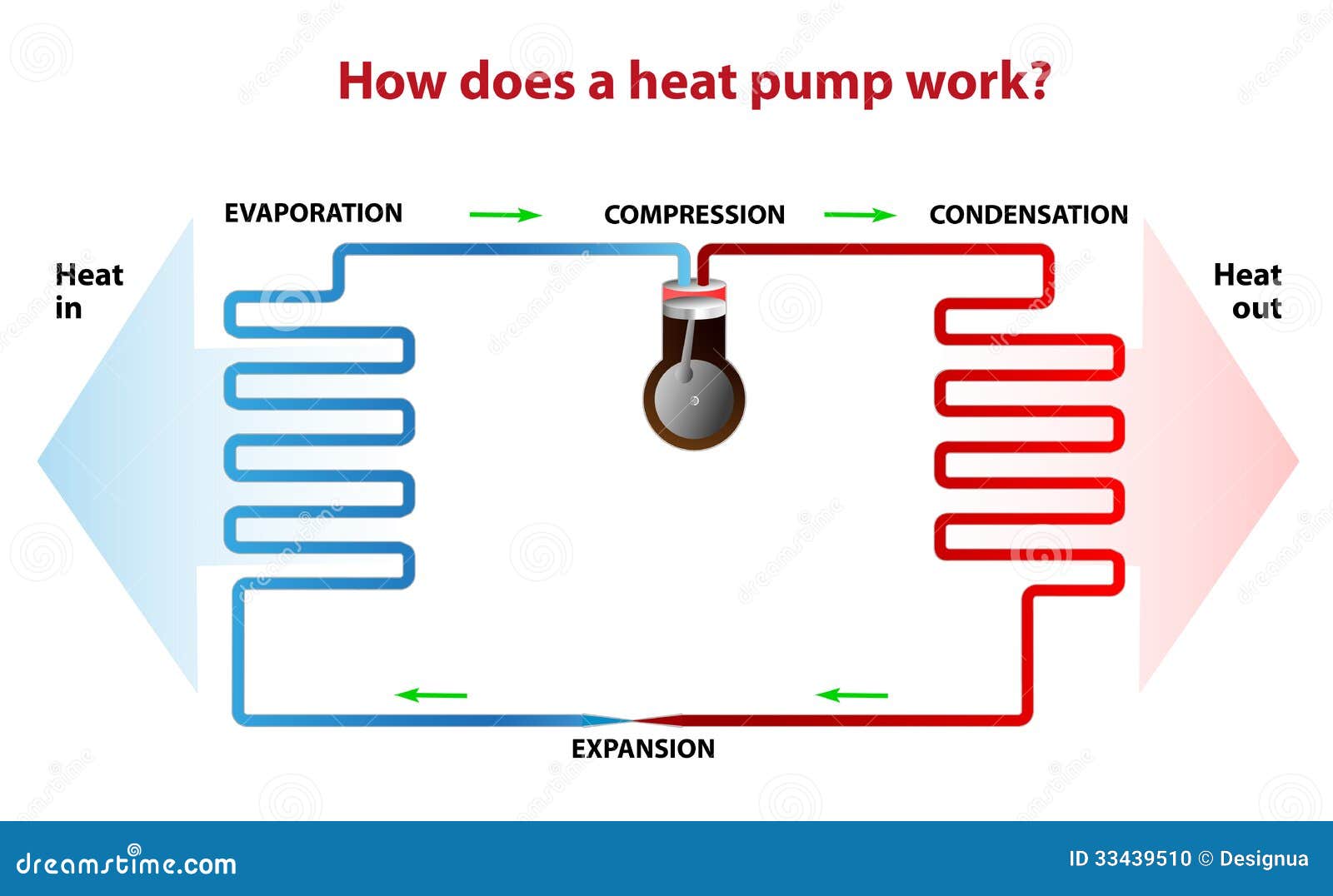
how does heat pump work works similarly like refrigerator heating season outside to inside opposite 33439510, image source: www.dreamstime.com

a simple chilled water system, image source: talkintrashwithuhn.com
289057 caraircon, image source: htauto.net

09 AT Rycroft HVAC energy efficiency fig01, image source: www.ee.co.za


220px Air_conditioning_unit en, image source: en.wikipedia.org
7, image source: dairyprocessinghandbook.com

Vortex Tube, image source: www.pftforum.com

hvac maine 11, image source: specialtyservicesme.com

Mircom Conventional Panel wiring diagram, image source: ipewo.com

1 602x330, image source: www.electricaltechnology.org

pict hvac ductwork symbols design elements hvac ductwork, image source: conceptdraw.com
How Chillers AHU and RTU work 1, image source: theengineeringmindset.com

Engineering Electrical Design Elements Qualifying, image source: www.conceptdraw.com


915qob%2B3xyL, image source: brokeasshome.com


Comments
Post a Comment