21 Awesome Gas Compressor Diagram

Gas Compressor Diagram gas condensate is a low density mixture of hydrocarbon liquids that are present as gaseous components in the raw natural gas produced from many natural gas fields Some gas species within the raw natural gas will condense to a liquid state if the temperature is reduced to below the hydrocarbon dew point temperature at a set pressure The natural gas condensate Gas Compressor Diagram folk ntnu no cadorao courses TEP10 files TEP10 Natural Gas 2 3 Hammerfest LNG plant block flow diagram Slug catcher Inlet facilities Metering CO2 removal De hydration Mercury removal Natural gas liquefaction LPG Storage
silverado mk3 third Chevrolet Silverado mk3 Third Generation 2014 2015 fuse box diagram Year of production 2014 2015 Engine Compartment Fuse Block The engine compartment fuse block is in the engine compartment on the driver side of the vehicle Gas Compressor Diagram
of the ambient conditions on gas turbine combined cycle power plants with post combustion CO 2 capture Gas Compressor Diagram
Gas Compressor Diagram Gallery

Gas_engine_poeser, image source: eugine.eu
bais_diagram_transparent, image source: www.csicompressco.com
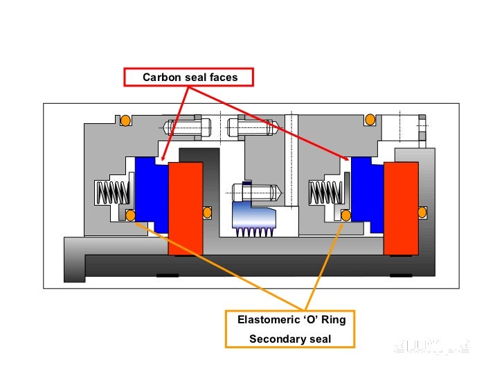
dry gas seal presentation 5 728, image source: www.slideshare.net

ek306 hvacr filter driers are installed in thermoking throughout thermo king refrigeration units piping diagrams, image source: sportbig.com

accumulators promo, image source: www.hydraulicspneumatics.com

centrifugal%2Bcompressor%2Bschematic%2Bdiagram, image source: www.mecholic.com

maxresdefault, image source: www.youtube.com
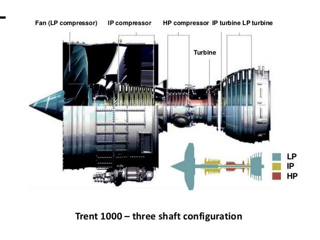
trent 1000 presentation 37 638, image source: www.slideshare.net
oil circuit breaker content 2 compressor, image source: circuitglobe.com
th?id=OGC, image source: world.honda.com
how_a_heat_pump_works2a, image source: www.isoenergy.co.uk
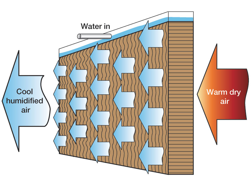
know evap cool, image source: www.condair.com
Backup_200107_mist_fig_3, image source: www.machinerylubrication.com
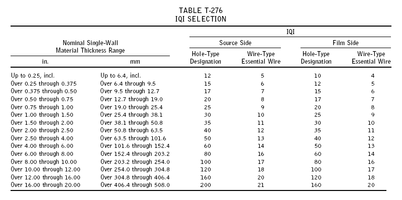
iqi selection, image source: www.inspection-for-industry.com

wet_scrubber_diagram_1, image source: www.ozonesolutions.com
Engel Fig 06, image source: www.gasprocessingnews.com
UTR Plus Compressor of Samsung Split Air Conditioner AC, image source: www.reviewcenter.in
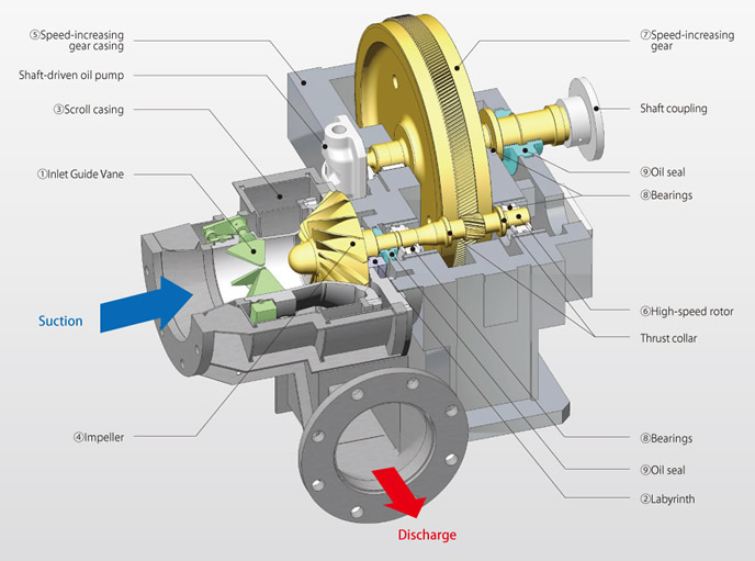
Structure_Steam, image source: global.kawasaki.com

hqdefault, image source: www.youtube.com
220px Package_type_cooling_tower, image source: en.wikipedia.org

Comments
Post a Comment