20 Inspirational Aluminum Copper Phase Diagram
Aluminum Copper Phase Diagram included copper alloy traveling nut also known as a carriage nut features a mounting flange with four holes threaded for M3 screws The nut moves 8 0 mm per full revolution of the lead screw which allows for a linear resolution of 0 040 mm per full step of the stepper motor Aluminum Copper Phase Diagram
Aluminum Copper Phase Diagram
Aluminum Copper Phase Diagram
Aluminum Copper Phase Diagram Gallery

Cu Al, image source: copper.zohosites.com
fig1_lg 1 1, image source: vacaero.com
pd_brass, image source: www.tf.uni-kiel.de

main qimg 63a9a2a050a98d735871e27a4b3f7551, image source: www.quora.com
Copalloys%202 3, image source: www.calqlata.com

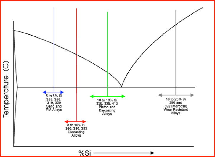
graph, image source: www.mercalloy.com
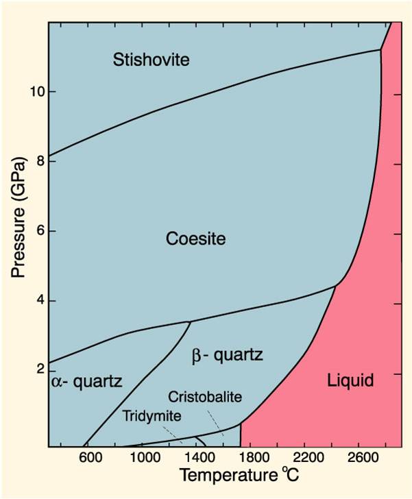
sio2, image source: www.odicis.org

fig06, image source: www.engr.sjsu.edu


1200px Gold aluminium_intermetallic, image source: en.wikipedia.org
Cooling+Curve, image source: slideplayer.com


brittle_to_ductile_general, image source: www.tf.uni-kiel.de
4HhlA, image source: electronics.stackexchange.com
3 Port AlumiConn 611, image source: www.diagramschematics.us

GEAFOL%20Transformer, image source: myelectrical.com

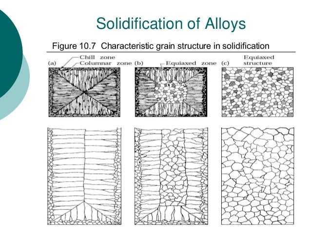
topic 3 metal casting 160214 7 638, image source: www.slideshare.net
hendrixfaq7, image source: keyboard-keys.info

2_pole_single_phase_basic, image source: cleantechnica.com

sensorbasics_eddy_current_img_03, image source: www.keyence.com

HTB1QMW8JFXXXXcAXpXXq6xXFXXXk, image source: advirnews.com


Comments
Post a Comment