20 Inspirational 2 Cycle Engine Diagram
2 Cycle Engine Diagram partstree Engines Vertical 4 Cycle Engine4 Cycle Equipment A basic spring service performed each year should include at least the following Check the Oil and inspect for contaminants such as water milky fuel too full thin and smells of gas or metal particles 2 Cycle Engine Diagram Carnot heat engine is a theoretical engine that operates on the reversible Carnot cycle The basic model for this engine was developed by Nicolas L onard Sadi Carnot in 1824 The Carnot engine model was graphically expanded upon by Beno t Paul mile Clapeyron in 1834 and mathematically explored by Rudolf Clausius in 1857 from which
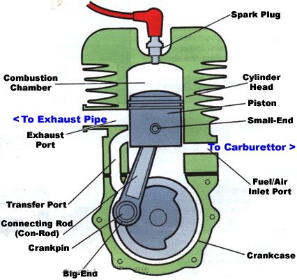
animatedengines twostroke htmlThe two stroke engine employs both the crankcase and the cylinder to achieve all the elements of the Otto cycle in only two strokes of the piston 2 Cycle Engine Diagram Otto cycle is an idealized thermodynamic cycle that describes the functioning of a typical spark ignition piston engine page needed It is the thermodynamic cycle most commonly found in automobile engines The Otto cycle is a description of what happens to a mass of gas as it is subjected to changes of pressure temperature volume mechanicalbooster 2017 10 otto cycle htmlThe Otto cycle was given by Dr Nikolaus August Otto It is a gas power cycle that is used in spark ignition engine i e petrol engine for its working The entire modern petrol engine works on Otto cycle
animatedengines otto htmlFour Stroke Engine The four stroke engine was first demonstrated by Nikolaus Otto in 1876 1 hence it is also known as the Otto cycle The technically correct term is actually four stroke cycle The four stroke engine is probably the most common engine 2 Cycle Engine Diagram mechanicalbooster 2017 10 otto cycle htmlThe Otto cycle was given by Dr Nikolaus August Otto It is a gas power cycle that is used in spark ignition engine i e petrol engine for its working The entire modern petrol engine works on Otto cycle ignou ac in upload Unit 2 32 pdf19 2 2 2 Theoretical Vapour Compression Cycle with Dry Saturated Refrigeration Cycle Vapour after Compression A vapour compression cycle with dry saturated vapour after compression is shown on T s
2 Cycle Engine Diagram Gallery

2 stroke 1, image source: www.makingdifferent.com
kobe, image source: www.blackhatmarine.com
2 stroke advantages 92454998, image source: www.pearltrees.com

2015 miller cycle engine diagram, image source: driventowrite.com

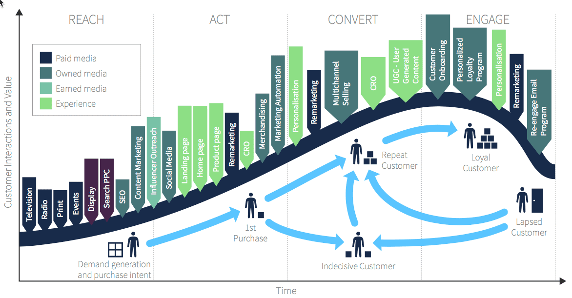
customer lifecycle B2C retail, image source: www.smartinsights.com

graphic small1, image source: dieselgrossisten.no
12, image source: www.defproac.com

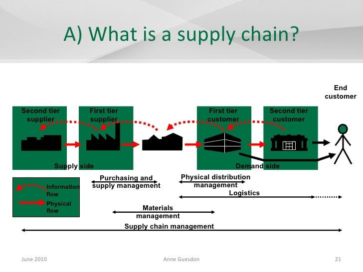
supply chain management in the motor vehicle industry the example of mini 21 728, image source: www.slideshare.net
alpine tundra food chain diagram photo collection for, image source: cssmith.co
cat d3406 propulsion 19151_1b, image source: www.fandjexports.com
ciclos otto diesel comparados, image source: www.stefanelli.eng.br
external nose anatomy diagram horse cranium sutures of the head, image source: cssmith.co
KZ650 F1, image source: diagrams.kz650.info

mozio bigger2, image source: www.tnooz.com
index_il04, image source: global.kawasaki.com
mcneb_36, image source: www.fixya.com
Old_Kawasaki_Single_Seat_Mule_compressed, image source: www.cheapcycleparts.com
th?id=OGC, image source: www.engineworld.fr

300px 2012_Honda_NC700SA, image source: en.wikipedia.org
Comments
Post a Comment