20 Elegant Encoder And Decoder Circuit Diagram And Truth Table

Encoder And Decoder Circuit Diagram electronics decoder encoderDecoder is a circuit which converts the digital signal into analog signal Its input will be in digital form while the output will be a continuous sine wave or analog wave Decoder Encoder Encoder And Decoder Circuit Diagram learnabout electronics Digital dig44 phpEncoders and Decoders What you ll learn in Module 4 6 Although the encoder circuits described in this module may be used in a number of useful encoding situations they have some features that limit their use for realistic keyboard encoding A decoder is a combinational logic circuit that takes a binary input usually in a coded form
drifter1 logic design multiplexer Logic Design Multiplexer Encoder and Decoder Circuits We will have to write a Circuit for an Encoder using the Inputs and Outputs of an Truth Table that represents the functionality of such an Encoder As I already said the Decoder is the opposite of an Encoder so using the Outputs of an Encoder as Inputs in it s corresponding Encoder And Decoder Circuit Diagram between encoder and Encoder vs Decoder In modern technological environment transmitting storing and interpreting information plays a key role in the operation of all the electronic based systems whether it is a digital device or an analog device or a computer system or a software system allaboutcircuits Worksheets Digital CircuitsDraw a simple schematic diagram showing how a digital encoder and decoder circuit pair could be used to relay the same fifteen commands across fewer cable conductors compared to if we used one conductor per pushbutton switch
circuit is a circuit in which we combine the different gates in the circuit for example encoder decoder multiplexer and demultiplexer Some of the characteristics of combinational circuits are following Full adder is developed to overcome the drawback of Half Adder circuit It Encoder And Decoder Circuit Diagram allaboutcircuits Worksheets Digital CircuitsDraw a simple schematic diagram showing how a digital encoder and decoder circuit pair could be used to relay the same fifteen commands across fewer cable conductors compared to if we used one conductor per pushbutton switch vidyarthiplus in 2012 01 digital logic circuitsencoder and htmlAn encoder is a combinational circuit that performs the inverse operation of a decoder If a device output code has fewer bits than the input code has the device is usually called an encoder e g 2 n to n priority encoders
Encoder And Decoder Circuit Diagram Gallery
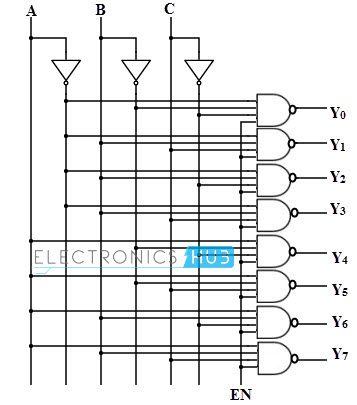
3 to 8 binary decoder logic diagram using NAND gates, image source: www.electronicshub.org
datasheet dual line decoder page san mao pdf_2 to 4 decoder_compressor motor wiring diagram electric timer control connections single phase forward and reverse direct online circu, image source: farhek.com

sensor_30, image source: www.ni.com

two to four decoder, image source: faculty.kfupm.edu.sa

audio_codec_schematic, image source: www.johnloomis.org


comb32, image source: www.electronics-tutorials.ws
5 channel remote control receiver, image source: www.circuitstoday.com

image011, image source: www.edwardbosworth.com

rc car electronic, image source: embedjournal.com

w3l1p4, image source: www.dcs.gla.ac.uk

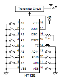
ht12e, image source: gzalo.com

Voice_Controlled_Robotic_Vehicle_with_Long_Distance_Speech_Recognition_Tx_Block_Diagram, image source: www.edgefxkits.com
2011329211525351, image source: www.seekic.com

HT12E_0, image source: www.engineersgarage.com
2011329211320620, image source: www.seekic.com


transmitter_circuit, image source: www.robomart.com
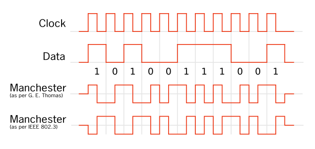
650px Manchester_encoding_both_conventions, image source: en.wikipedia.org

types of encoders and decoders with truth tables 5 638, image source: pt.slideshare.net
10m txfront, image source: www.pg1n.nl


Comments
Post a Comment