19 Unique Lm324 Circuit Diagram
Lm324 Circuit Diagram circuitsLM324 Circuits and Projects 6 LM224 LM324 series consists of four independent high gain internally frequency compensated operational amplifiers which Diode Digital Thermometer Circuit Received by Email 12 05 2009 This digital thermometer circuit diagram uses a common 1N4148 diode as the temperature sensor The temperature Lm324 Circuit Diagram D PDFLM324 D LM324 LM324A LM324E LM224 LM2902 LM2902E LM2902V NCV2902 Single Supply Quad Representative Circuit Diagram One Fourth of Circuit Shown Output Bias Circuitry Common to Four Amplifiers VCC VEE GND Inputs Q2 Q3 Q4 Q5 Q26 Q7 Q8 Q6 Q9 Q11 Q10 Q1 2 4 k Q25 Q22 40 k Q13 Q14 Q15 Q16 Q19 5 0 pF Q18 Q17 Q20 Q21 2 0 k Q24 Q23 Q12
components lm324n datasheetLM324 is a 14pin IC consisting of four independent operational amplifiers op amps compensated in a single package Op amps are high gain electronic voltage amplifier with differential input and usually a single ended output Lm324 Circuit Diagram gauge circuit using lm324 icWe use the LM324 integrated circuit having four 741 operational amplifiers Op Amp in a single package The temperature gauge circuit diagram shows a voltage divider network made with R2 R3 R4 R5 and R6 resistors 4 For operating at high temperatures the LM324 LM324A LM2902 must be derated based on a 125 C maximum junction temperature and a thermal resistance of 88 C W which applies for the device soldered in a printed circuit board operating in a still air ambient
comparator ic working applicationsComparator Circuit Using LM324 The following circuit shows the Voltage comparator the components required for this circuit is the LM324 comparator and the two resistors with a value of 10K ohms Lm324 Circuit Diagram 4 For operating at high temperatures the LM324 LM324A LM2902 must be derated based on a 125 C maximum junction temperature and a thermal resistance of 88 C W which applies for the device soldered in a printed circuit board operating in a still air ambient to view on Bing0 41Nov 23 2010 Schematics for building the 0 100 duty cycle PWM Author SolarNovaViews 38K
Lm324 Circuit Diagram Gallery
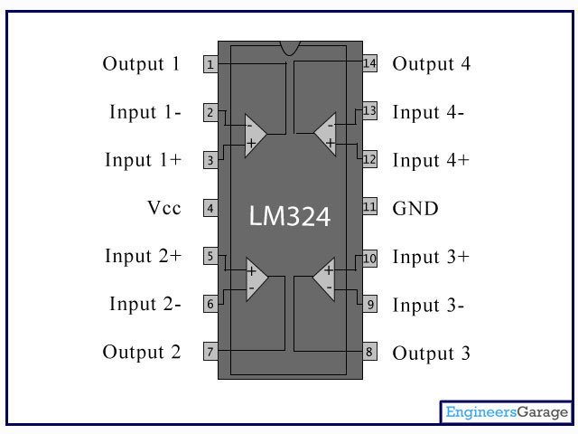
LM324_1, image source: www.engineersgarage.com
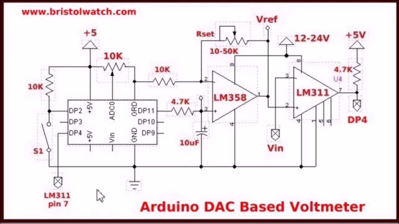
maxresdefault, image source: www.youtube.com

G4taD, image source: electronics.stackexchange.com
Build a Great Sounding Audio Amplifier with Bass Boost from the LM386 Amplifier With Bass Boost Schematic, image source: www.circuitbasics.com

dc motor controller, image source: www.circuitstoday.com

Electronics mini projects4, image source: www.electronics.engineeringminiprojects.com

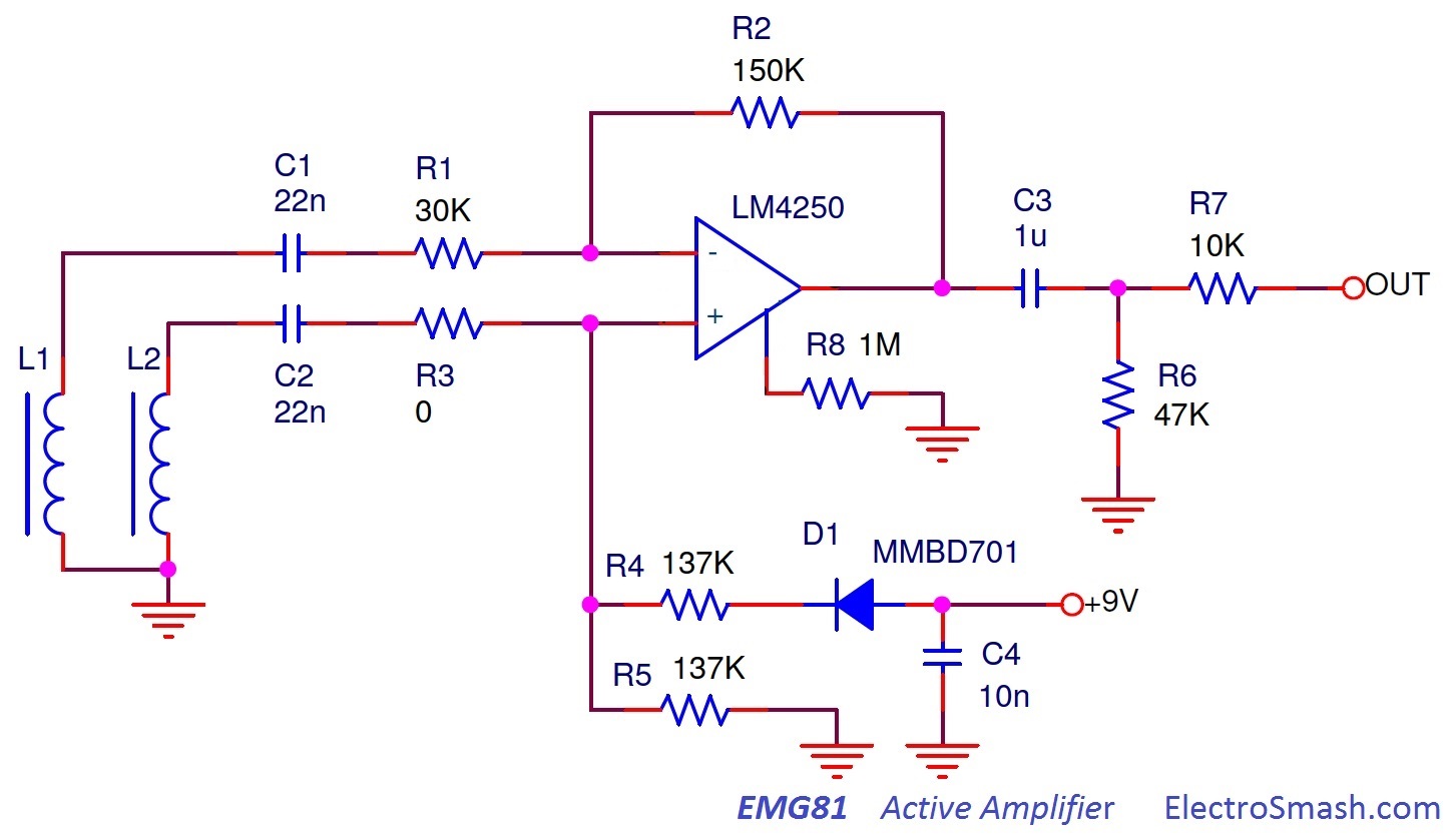
emg81 schematic, image source: www.electrosmash.com

stop%2Bwatch%2Bcircuit, image source: www.homemade-circuits.com
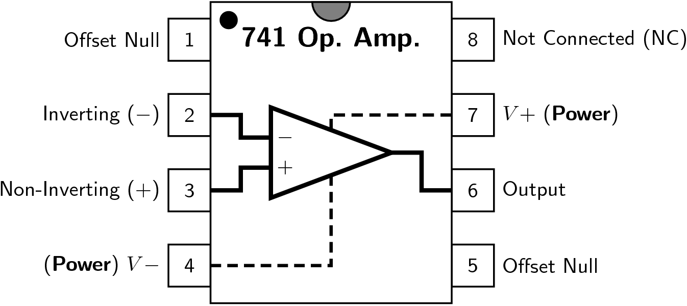
Generic_741_pinout_top, image source: commons.wikimedia.org
temperature controlled leds, image source: www.circuitstoday.com


am, image source: electronicsproject.org
load, image source: www.kerrywong.com

How to use LDR Sensor in Proteus6, image source: www.theengineeringprojects.com

semi tech com sg ses wet bench products are used in such stage of semiconductor production process_semiconductor manufacturing_best dual battery isolator ceramic oscillator 55, image source: farhek.com

opamp tester circuit, image source: circuitdigest.com

Operational+Amplifier, image source: blogdealbuelo.blogspot.com
yihua hakko 936 schematic aoyue 936 schematic hakko 936 schematic, image source: 320volt.com

Controle de Motor DC com PWM, image source: blog.novaeletronica.com.br


Comments
Post a Comment