19 Luxury Uml Component Diagram Tutorial

Uml Component Diagram Tutorial sparxsystems resources uml2 tutorial uml2 componentdiagram UML 2 Tutorial Component Diagram Component Diagrams Component diagrams illustrate the pieces of software embedded controllers etc that will make up a system A component diagram has a higher level of abstraction than a Class Diagram usually a component is implemented by one or more classes or objects at runtime Uml Component Diagram Tutorial component diagram notation set now makes it one of the easiest UML diagrams to draw Figure 1 shows a simple component diagram using the former UML 1 4 notation the example shows a relationship between two components an Order System component that uses the Inventory System component
diagram tutorialWhile other UML diagrams which describe the functionality of a system component diagrams are used to model the components that help make those functionalities In this component diagram tutorial we will look at what a component diagram is component diagram symbols and how to Uml Component Diagram Tutorial component diagramWhat is a UML component diagram The purpose of a component diagram is to show the relationship between different components in a system For the purpose of UML 2 0 the term component refers to a module of classes that represent independent systems or subsystems with the ability to interface with the rest of the system diagramA component diagram also known as a UML component diagram describes the organization and wiring of the physical components in a system Component diagrams are often drawn to help model implementation details and double check that every aspect of the system s required functions is covered by planned development
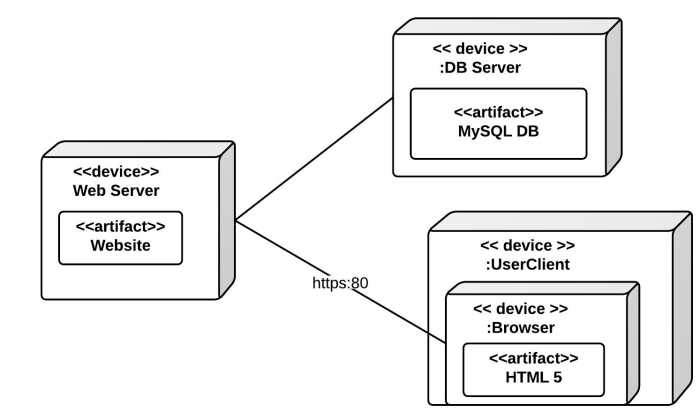
paradigm component diagram tutorialComponent Diagram Example Components in Deployment Diagram Models the physical deployment of software components with UML deployment diagram In deployment diagram hardware components e g web server mail server application server are presented as nodes with the software components that run inside the hardware components presented as Uml Component Diagram Tutorial diagramA component diagram also known as a UML component diagram describes the organization and wiring of the physical components in a system Component diagrams are often drawn to help model implementation details and double check that every aspect of the system s required functions is covered by planned development agilemodeling artifacts componentDiagram htmFigure 1 presents an example component model using the UML 2 notation for the university system Figure 2 depicts the same diagram using UML 1 x notation As you can see there are several notational differences
Uml Component Diagram Tutorial Gallery

component_diagram_ATM_system 843x746, image source: www.lucidchart.com
uml class diagram notation, image source: www.conceptdraw.com

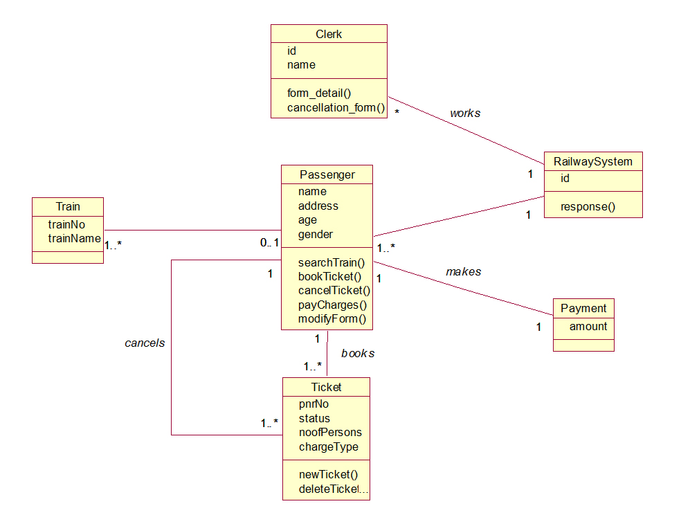
RRS Class Diagram, image source: startertutorials.com
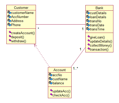
OBNS Class Diagram, image source: www.startertutorials.com
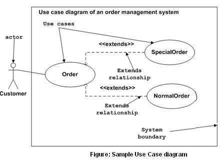
uml_use_case_diagram, image source: www.tutorialspoint.com
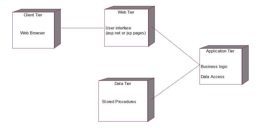
LMS Deployment Diagram, image source: www.startertutorials.com
uml+activity+diagram+for+vending+machine, image source: itkaka786.blogspot.kr
deployment diagram example 700x412, image source: www.lucidchart.com

patient+state+chart+diagram+hospital+mgmt, image source: itkaka786.blogspot.com
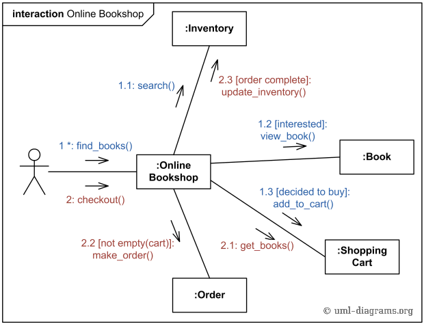
communication examples online bookshop, image source: ccuart.org
exampleofarequirementsdiagram, image source: www.sparxsystems.com

DZ400 2D vacuum packing machine for food, image source: elsalvadorla.org


RRS Deployment Diagram, image source: umldp.blogspot.com

activity+diagram+patient+payment+hospital+mgmt, image source: itkaka786.blogspot.com

Natural_Draft, image source: ccuart.org
3D_Shapes, image source: www.edrawsoft.com

BLOCK%2BDIA, image source: komal-educationtutorial.blogspot.com

watermelon diet to lose weight, image source: ccuart.org


Comments
Post a Comment