19 Images Logical System Diagram

Logical System Diagram pedagogy and theoretical syntax a sentence diagram or parse tree is a pictorial representation of the grammatical structure of a sentence The term sentence diagram is used more in pedagogy where sentences are diagrammed The term parse tree is used in linguistics especially computational linguistics where sentences are parsed Their purposes are to demonstrate the structure of sentences Logical System Diagram paradigm tutorials data flow diagram Data Flow Diagram DFD provides a visual representation of the flow of information i e data within a system By creating a Data Flow Diagram you can tell the information provided by and delivered to someone who takes part in system processes the information needed in order to complete the processes and the information needed to be stored and accessed
agilemodeling artifacts dataFlowDiagram htmIn the late 1970s data flow diagrams DFDs were introduced and popularized for structured analysis and design Gane and Sarson 1979 DFDs show the flow of data from external entities into the system showed how the data moved from one process to another as well as its logical storage Logical System Diagram flow diagramWhat is a data flow diagram A data flow diagram DFD maps out the flow of information for any process or system It uses defined symbols like rectangles circles and arrows plus short text labels to show data inputs outputs storage points and the routes between each destination paradigm docs database design Conceptual logical and physical model or ERD are three different ways of modeling data in a domain While they all contain entities and relationships they differ in the purposes they are created for and audiences they are meant to target
chapter describes the nature of and relationships among logical storage structures These structures are created and recognized by Oracle Database and are not known to the operating system Logical System Diagram paradigm docs database design Conceptual logical and physical model or ERD are three different ways of modeling data in a domain While they all contain entities and relationships they differ in the purposes they are created for and audiences they are meant to target agilemodeling style activityDiagram htmThe Elements of UML 2 0 Style describes a collection of standards conventions and guidelines for creating effective UML diagrams They are based on sound proven software engineering principles that lead to diagrams that are easier to understand and work with
Logical System Diagram Gallery
network diagram example, image source: www.businessphrases.net

osi model diagram layers, image source: www.printablediagram.com

api management vnet external, image source: docs.microsoft.com
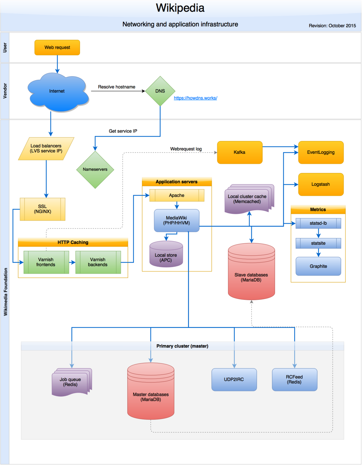
1200px Wikipedia_webrequest_flow_2015 10, image source: meta.wikimedia.org
main qimg fe035ea86d6bc8e2594ecf0c98fdb4bb, image source: www.quora.com
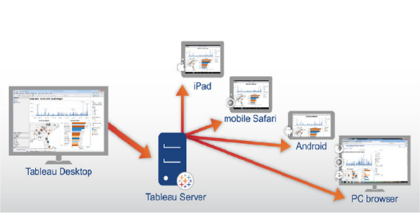
Tableau Architecture, image source: intellipaat.com

aem forms jee architecture, image source: helpx.adobe.com
221014, image source: www.cisco.com

Azure Stack Architecture Overview, image source: azurestack.blog
documentation of railway reservation system 18 638, image source: www.slideshare.net
sad 11 638, image source: www.slideshare.net
70519 Anatomy Chart The Female Reproductive System_media 01, image source: ccuart.org

3D Wire Routing hi Res e1351719469160, image source: gfxspeak.com

telecommunications_management_network, image source: tech-talk.org
soacs_atom_pattern, image source: www.ateam-oracle.com

intel i3i5i7 processor 5 638, image source: www.slideshare.net

pict router cisco routers vector stencils library, image source: www.conceptdraw.com
Modern Data Center, image source: blog.trendmicro.com
Comments
Post a Comment