19 Best Wireless Intercom Circuit Diagram

Wireless Intercom Circuit Diagram tech online threads full duplex wireless Mar 16 2015 Good day everyone I need some help here Do you have any ideas suggestions to make this circuit diagram to become a full duplex wireless intercom Wireless Intercom Circuit Diagram circuit finder categories telephone related intercom page 1This is the circuit that sparked off all the other Link Telephone Intercom designs Originally designed back in 1996 with heavy duty relays and their contact banks it was updated late last year with the
circuits two way intercomThe speaker volume can be adjusted with the help of variable resistor VR1 For the circuit to operate as two way intercom make two identical circuits as shown in circuit diagram Wireless Intercom Circuit Diagram circuitsgallery 2012 12 Simple Intercom Circuit htmlIntercom or Inter communication circuit is a two directional communication system It provides a reliable communication line and is extremely easy to implement The circuit is prepared by an amplifier two switches and two loudspeakers circuitsgallery 2013 09 Door phone intercom circuit htmlSimple Door Phone Intercom Circuit Schematic Duplex Gallery of Electronic Circuits and projects providing lot of DIY circuit diagrams Robotics Microcontroller Projects Electronic development tools Menu Skip to content The main component used here in this two way intercom circuit is an 1895 IC It is a 1 watt audio amplifier
brighthubengineering DIY Digital Analog ElectronicsA very simple yet highly efficient circuit design for a home intercom system is covered under this article The system once built can be effectively used to communicate discretely across ten rooms in a house or an apartment with just a press of a button Wireless Intercom Circuit Diagram circuitsgallery 2013 09 Door phone intercom circuit htmlSimple Door Phone Intercom Circuit Schematic Duplex Gallery of Electronic Circuits and projects providing lot of DIY circuit diagrams Robotics Microcontroller Projects Electronic development tools Menu Skip to content The main component used here in this two way intercom circuit is an 1895 IC It is a 1 watt audio amplifier way intercom circuit diagramThe complete circuit diagram of this Intercom Project is given below As you can see the circuit is very simple and can be easily built over a breadboard The main concept behind the circuit is the use of LM386 audio amplifier which receives the audio signal from microphone amplifies it
Wireless Intercom Circuit Diagram Gallery
computer circuit diagram zen_small circuit diagram_building wiring system electronic project circuit diagram typical digital camera electrical wire roll telephone electric symbols, image source: farhek.com

AiphoneIntercomWiringDiagram1, image source: circuitswiring.com


proxy, image source: forum.allaboutcircuits.com
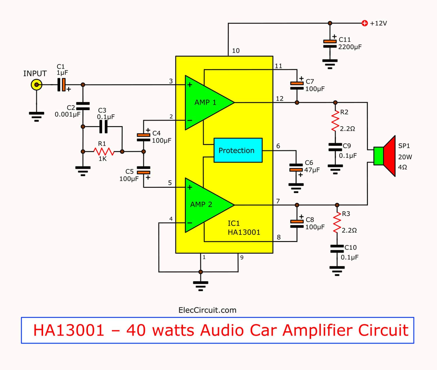
mini 40 watt audio car amplifiers using ha13001, image source: ccuart.org
Ott23, image source: electronics.stackexchange.com

arduino esp8266 breadboard, image source: elsalvadorla.org

balanced xlr wiring diagram pic chevy axle actuator wire inside, image source: snicespa.com

Air Conditioning Compressor controller Circuit Diagram, image source: www.afiata.com


loop powered, image source: thaymanhinhipad.info
digitalAfterInstall_bb_1 1, image source: edmiracle.co


eartec_ul4d_ultralite_4_person_headset_1269361, image source: elsalvadorla.org
Driver Relay using CD4024B CD4068B CD4028 BC148 SL100, image source: www.afiata.com

Battery Charger using 78L12 555 MOC3041 4060, image source: www.afiata.com

doorbellhookup, image source: www.wiringdoneright.com


how to install a home security system 1, image source: home.howstuffworks.com
hqdefault, image source: www.youtube.com

surprising nutone bathroom fan wiring diagram pictures with exhaust, image source: readyjetset.co

27MHz Citizens Band Using TR SC1675 SC828 SA564 SA715SC1383 SC1909 and IC TA7205 724x1024, image source: www.afiata.com


Comments
Post a Comment