17 Luxury Ceiling Fan Circuit Diagram
Ceiling Fan Circuit Diagram it yourself help wiring diagram ceilingfan htmlWiring a Fan Light Kit to 3 Way Switches To wire a 3 way switch circuit that controls both the fan and the light use this diagram As with all 3 way circuits the common on one switch is connected to the hot source wire from the circuit Ceiling Fan Circuit Diagram ceiling fans n more ceiling fan wiring phpCeiling Fan Wiring Instructions by Wire Color Wiring a ceiling fan is surprisingly simple Often times it is no more complicated than the wiring of a light fixture As with any electrical wiring make sure all wire connections are made securely with the proper size wire nuts that they are not loose and that no copper strands are showing
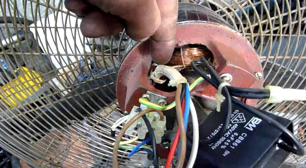
jestineyong panasonic ceiling fan repairPanasonic Ceiling Fan Repaired By JestineYong Note A shorted semiconductor could cause a circuit to cease operation thus it is a good practice to check on other components also Since I do not have the schematic diagram I have to view the circuit from the back and to find out why this capacitor could cause the fan not to function Ceiling Fan Circuit Diagram to replace a ceiling fan motor This project explains how to replace a ceiling fan that won t turn by replacing a blown motor capacitor Total cost of the repair was 12 for a new motor capacitor 8 for the capacitor plus 4 shipping manualslib Hunter Manuals Fan Hunter Ceiling FanView and Download Hunter Ceiling fan installation manual online ceiling fan Ceiling fan Fan pdf manual download
fix ceiling fan doesnt work htmlCeiling Fan Doesn t Work At All Be sure to turn off the fan s circuit breaker before disassembling the fan or its switch These are instructions for troubleshooting a fan that is completely dead Ceiling Fan Circuit Diagram manualslib Hunter Manuals Fan Hunter Ceiling FanView and Download Hunter Ceiling fan installation manual online ceiling fan Ceiling fan Fan pdf manual download to wire a single switch ceiling fanConnect the remaining ceiling fan wires to the circuit wires following the fan manufacturer s wiring diagram In a typical installation the white neutral fan wire connects to the white neutral circuit wire and the black hot fan wire connects to the black hot circuit wire
Ceiling Fan Circuit Diagram Gallery
me08 and wiring a alternator diagram, image source: kanri.info

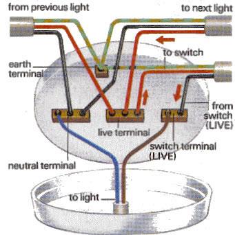
Basic lighting circuit, image source: www.sparkyfacts.co.uk


Fan Coil Layout, image source: www.designbuilder.co.uk
attachment, image source: www.ford-trucks.com
full, image source: www.diynot.com
branch circuits pr, image source: www.ecmweb.com

maxresdefault, image source: www.youtube.com
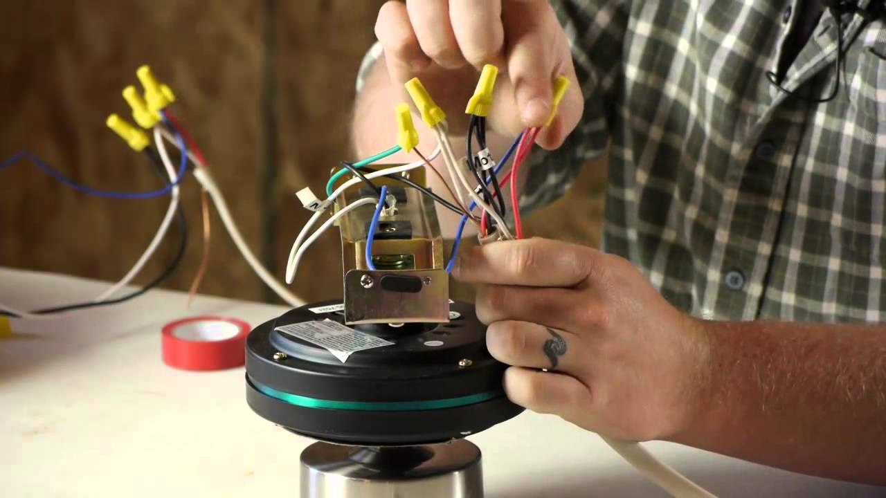
maxresdefault, image source: www.youtube.com

circuit breaker service panel, image source: www.do-it-yourself-help.com
FS VRF VRV System, image source: www.achrnews.com

potential feature image 1_1200x750, image source: gnomadhome.com
1_22_14, image source: www.partdeal.com


300px Knob_and_tube_1930, image source: en.wikipedia.org
pontiac montana fuse box instrument panel 2005, image source: www.autogenius.info


aid1555656 v4 728px Wire a Potentiometer Step 1 Version 2, image source: www.wikihow.com
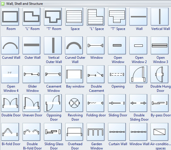
wall shell structure, image source: www.edrawsoft.com


Comments
Post a Comment