17 Best 3 Bit Magnitude Comparator Circuit Diagram
3 Bit Magnitude Comparator Circuit Diagram forum allaboutcircuits Education Homework HelpMar 15 2005 Hello people can any one tell me how this can be done I m stuck on the following steps The question says that you have 3 bits A2 A1 A0 which are being compared to B2 B1 B0 3 Bit Magnitude Comparator Circuit Diagram ijesi papers Vol 2 1 version 2 C211324 pdfBlock Diagram of n Bit Magnitude Comparator The circuit for comparing two n Bit numbers has 2n inputs 2 2n entries in the truth table for 2 Bit numbers 4 inputs 16 rows in the truth table similarly for 3 Bit numbers 6 inputs 64 rows in the truth
readingrat Circuit diagram4 Bit Comparator Circuit Diagram The distinction between a standard move plus a three way transition is relationship or one added final A3 way change has 2 terminals which can be either one critical that s dark coloured and gold or steel coloured 3 Bit Magnitude Comparator Circuit Diagram datasheetarchive circuit diagram of 3 bit magnitude Abstract circuit diagram of 3 bit magnitude comparator MC10H166 5 Bit Magnitude Comparator The MC10H166 is a 5 Bit Magnitude Comparator and is a 1 9 BIT MAGNITUDE COMPARATOR A0 B0 A1 B1 A2 B2 A3 B3 A4 B4 A5 B5 A6 B6 A7 B7 A8 B8 A0 B0 A1 25 BIT MAGNITUDE COMPARATOR B24 A24 B23 A23 B22 A22 B21 learnabout electronics Digital dig43 phpA simple 1 bit magnitude comparator is shown in Fig 4 3 2 Gate 1 produces the function A B and gate 3 gives A B while gate 2 is an XNOR gate giving an equality output This basic circuit for a magnitude comparator may be extended for any number of bits but the more bits the circuit has to compare the more complex the circuit
comparator and magnitude The figure below shows the block diagram of a single bit magnitude comparator This comparator compares the two bits and produces one of the 3 outputs as L A B E A B and G A B The truth table for the single bit comparator is given below 3 Bit Magnitude Comparator Circuit Diagram learnabout electronics Digital dig43 phpA simple 1 bit magnitude comparator is shown in Fig 4 3 2 Gate 1 produces the function A B and gate 3 gives A B while gate 2 is an XNOR gate giving an equality output This basic circuit for a magnitude comparator may be extended for any number of bits but the more bits the circuit has to compare the more complex the circuit electronics tutorials ws Combinational LogicMagnitude Comparator a Magnitude Comparator is a digital comparator which has three output terminals one each for equality A B greater than A B and less than A B The purpose of a Digital Comparator is to compare a set of variables or unknown numbers for example A A1 A2 A3
3 Bit Magnitude Comparator Circuit Diagram Gallery
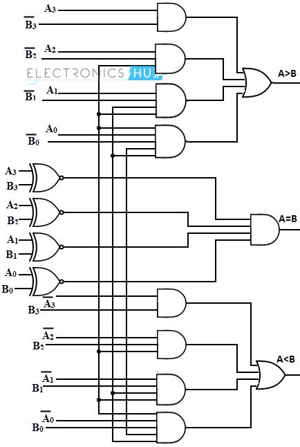
Logic Diagram of 4 bit Comparator, image source: www.electronicshub.org
4 bit+Magnitude+Comparator, image source: circuitartmattend.com
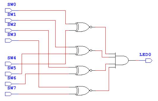
image4379750024932853841, image source: wiringdiagram.karaharmsphotography.com
circuit_diagram_n_bit_identity_comparator, image source: en.f-alpha.net
74L85, image source: web.eecs.umich.edu
prob6 5, image source: www.cecs.uci.edu
comparator equality, image source: www.learnabout-electronics.org
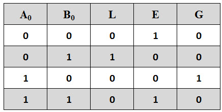
Single Bit Comparator Truth Table, image source: www.electronicshub.org
245 3vs, image source: estrategys.co

42adc227955144a1423749261365122a, image source: www.pinterest.co.uk
circuit_1_bit_magnitude_comparator_web, image source: en.f-alpha.net

hqdefault, image source: www.youtube.com

comb44, image source: www.electronics-tutorials.ws
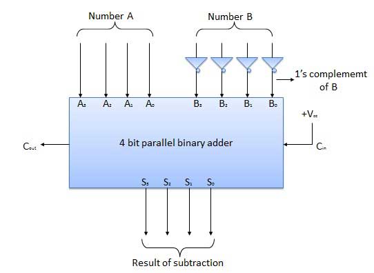
fourbitsubstractor_blockdiagram, image source: www.tutorialspoint.com
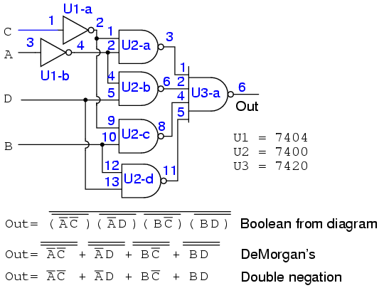
14149, image source: www.ibiblio.org
14157, image source: www.allaboutcircuits.com
Comments
Post a Comment