21 Elegant Ferrite Phase Diagram
Ferrite Phase Diagram ispatguru the iron carbon phase diagramThe Iron Carbon Phase Diagram In their simplest form steels are alloys of Iron Fe and Carbon C The study of the constitution and structure of iron and steel start with the iron carbon phase diagram Ferrite Phase Diagram ispatguru carbon steels and the iron carbon phase diagramCarbon Steels and the Iron Carbon Phase Diagram Steels are alloys having elements of iron Fe and carbon C C gets dissolved in Fe during the production of steels
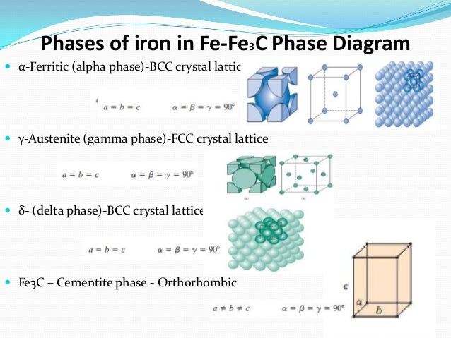
calphad iron titanium htmlPhase Diagrams Iron Titanium Fe Ti Phase Diagram A study of the precipitation hardening of iron titanium Fe Ti alloys usually starts with the iron titanium binary system Fe Ti based alloys are also used for storage of hydrogen in the form of metal hydride Figure 1 shows the iron titanium phase diagram up to 30 wt Ti calculated with Thermo Calc coupled with TCFE3 thermodynamic Ferrite Phase Diagram is ferrite cementite austenite and pearliteFERRITE which is called alpha and beta phase this ll come from room temp to 910 deg cent and also from 1310 deg cent to 1539 deg cent practicalmaintenance p 1345Phase Diagrams are limited in their usefulness because they can only predict the microstructure that will result for equilibrium conditions i e very very slow cooling
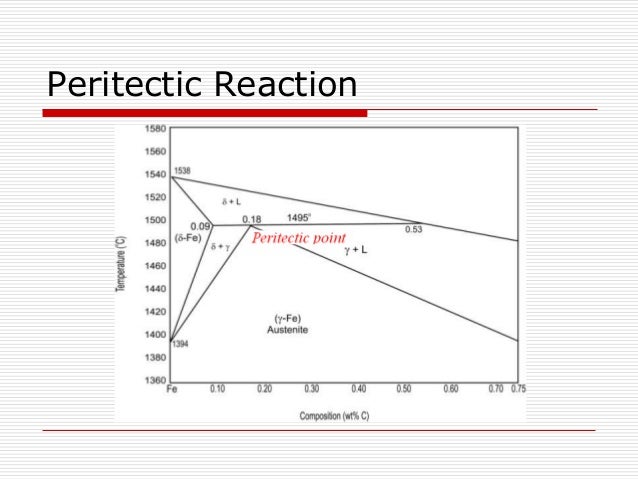
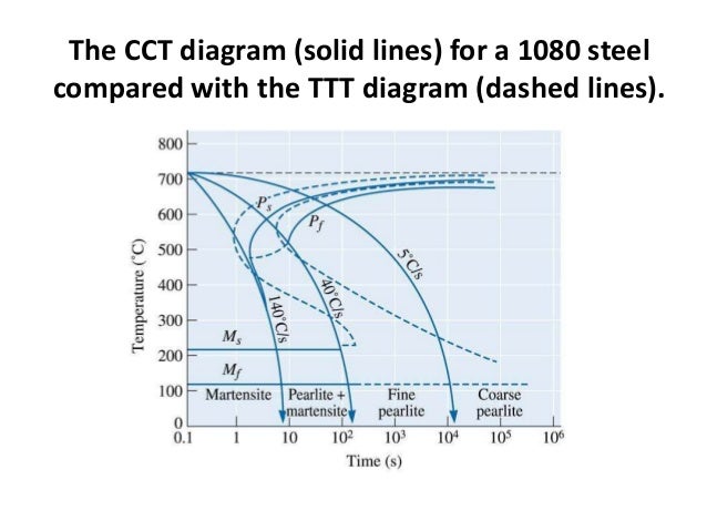
calphad iron carbon htmlA study of the microstructure of all steels usually starts with the metastable Fe C binary phase diagram It provides an invaluable foundation on which to build knowledge of both carbon steels and alloy steels as well as a number of various heat treatments they are usually subjected to Ferrite Phase Diagram practicalmaintenance p 1345Phase Diagrams are limited in their usefulness because they can only predict the microstructure that will result for equilibrium conditions i e very very slow cooling dierk raabe dual phase steelsDual phase steels DP steels consist of ferrite and a dispersed hard martensitic second phase in the form of islands Usually they are low carbon low alloy materials with 10 40 vol hard martensite or martensite austenite particles embedded in a ductile ferrite matrix As they combine high strength and good formability at low production costs they are widely used for automotive applications
Ferrite Phase Diagram Gallery

steel phase diagram printable, image source: www.printablediagram.com

The%20Schaeffler%20and%20Delong%20diagrams%20for%20predicting%20ferrite%20levels%20in%20austenitic%20stainless%20steel%20welds_2, image source: www.bssa.org.uk
metallurgy basics iron phase diagram 12 638, image source: www.slideshare.net

bd969801b55f9d385035868f005f8091, image source: www.pinterest.com
iron carbon diagram 10 638, image source: www.slideshare.net

carbon1, image source: www.gowelding.com

iron carbon phase diagram 7 638, image source: www.slideshare.net

fe_c_phase_diagram_cast_iron, image source: www.tf.uni-kiel.de

ironiron carbide phase diagrams 40 638, image source: www.slideshare.net
image_thumb 12, image source: www.mechscience.com


maxresdefault, image source: www.youtube.com

car amplifier power supply, image source: powersupply33.com
24Z_Fig_1, image source: electronicsforu.com
ttt diagram 72 638, image source: www.slideshare.net
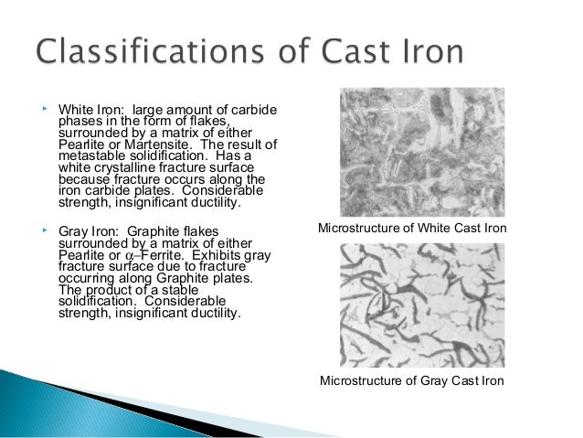
metallurgical properties of cast irons 4 638, image source: www.slideshare.net
AHSSDiagram_WorldAutoSteel copy, image source: www.worldautosteel.org


Correlation between hardness and yield strength for copper alloys 12 28, image source: www.researchgate.net
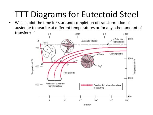
ttt diagram 33 638, image source: www.slideshare.net
image004, image source: www.azom.com


9d7eb2fcb8_50069185_2498 ff 068mini, image source: www.futura-sciences.com


Comments
Post a Comment