21 Lovely Cmos And Gate Circuit Diagram

Cmos And Gate Circuit Diagram eleccircuit Mini ProjectsSCR DC motor speed control circuit using IC CMOS This can use for DC motor and SCR1 The SCR need to uses DC to A K lead Which it uses just the pulsed DC only Cmos And Gate Circuit Diagram OR gate is a digital logic gate that implements logical disjunction it behaves according to the truth table to the right A HIGH output 1 results if one or both the inputs to the gate are HIGH 1 If neither input is high a LOW output 0 results In another sense the function of OR effectively finds the maximum between two binary digits just as the complementary AND function
between nmos cmos technologyThe most popular MOSFET technology semiconductor technology available today is the CMOS technology or complementary MOS technology CMOS technology is the leading semiconductor technology for ASICs memories microprocessors The main advantage of CMOS technology over BIPOLAR and NMOS technology is the power dissipation when the circuit is switches then only Cmos And Gate Circuit Diagram satsleuth Schematics aspxElectronic Circuit Schematics Note that all these links are external and we cannot provide support on the circuits or offer any guarantees to their accuracy circuitstoday simple 100w inverter circuit100Watt Inverter Circuit Inverter circuits are among the easiest circuits to build for newbies Here is the circuit diagram of a simple 100 watt inverter using IC CD4047 and MOSFET IRF540
circuitstoday 7 segment counter circuitSeven Segment Counter Display Circuit Description Here is the circuit diagram of a seven segment counter based on the counter IC CD 4033 This circuit can be used in conjunction with various circuits where a counter to display the progress adds some more attraction Cmos And Gate Circuit Diagram circuitstoday simple 100w inverter circuit100Watt Inverter Circuit Inverter circuits are among the easiest circuits to build for newbies Here is the circuit diagram of a simple 100 watt inverter using IC CD4047 and MOSFET IRF540 bowdenshobbycircuits page5 htmInterfacing 5 volt CMOS to 12 volt 25 Watt Loads The circuit below is designed to be used with the bi directional lamp sequencer shown above on this same page
Cmos And Gate Circuit Diagram Gallery
04324, image source: www.allaboutcircuits.com

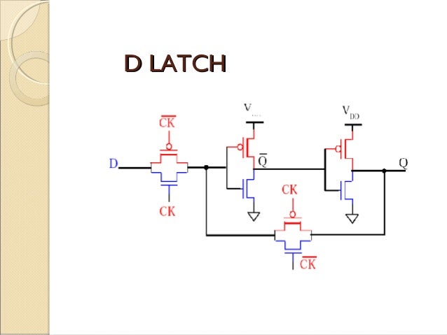
cmos flip flop, image source: www.indiabix.com
cmos logic circuits 11 638, image source: www.slideshare.net
fig1 2k15 478 489, image source: scialert.net

component logical and gate gates truth table klaus kohl teaching it logic pdf thumbnail_truth table to logic circuit_polyphase circuit logic gate timer wireless remote switch schemati_1100x773, image source: farhek.com

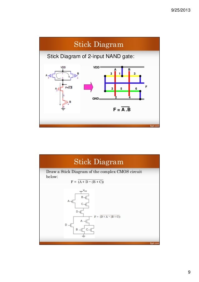
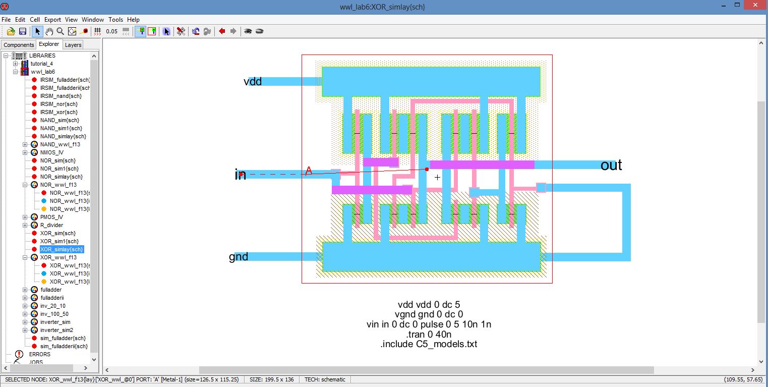
vlsi stick daigram jce 21 638, image source: www.slideshare.net
dc motor controller with scr ic cmos, image source: www.eleccircuit.com
pass transistor logic 20 638, image source: www.slideshare.net
cmos topic 6 designingcombinationallogiccircuits 9 638, image source: www.slideshare.net

5 Automatic led night light switch circuit, image source: www.eleccircuit.com

th?id=OGC, image source: iamtechnical.com

FNLLPR6GKI1A6AF, image source: www.instructables.com

fs, image source: mantravlsi.blogspot.in
counter up down sync, image source: www.learnabout-electronics.org
water pump relay controller circuit schematic_orig, image source: www.circuit-finder.com
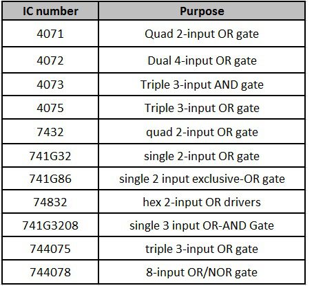
frequently used ics, image source: www.electronicshub.org

350px V to i_op amp_current_source_1000, image source: en.wikipedia.org
p17, image source: cmosedu.com

F5, image source: rsta.royalsocietypublishing.org

Paper 3, image source: semimd.com


Comments
Post a Comment