20 Fresh Inverter Battery Charger Circuit Diagram
Inverter Battery Charger Circuit Diagram battery charger circuitThis automatic battery charger circuit is mainly involves two sections power supply section and load comparison section The main supply voltage 230V 50Hz is connected to the primary winding of the center tapped transformer to step down the Inverter Battery Charger Circuit Diagram circuitsgallery 2012 07 simple low power inverter 6v dc to Working of DC to AC Inverter You must use a battery and battery charger to implement this inverter circuit Battery charging circuit
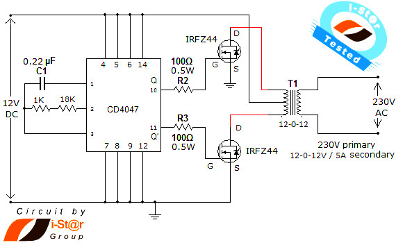
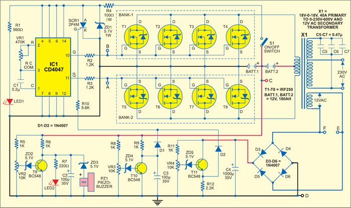
circuitstoday simple 100w inverter circuitInverter circuits are among the easiest circuits to build for newbies Here is the circuit diagram of a simple 100 watt inverter using IC CD4047 and MOSFET IRF540 The circuit is simple low cost and can be even assembled on a veroboard B1 can be a 12V 6Ah lead acid battery Q1 and Q2 must be Inverter Battery Charger Circuit Diagram circuitdiagramApache Server at circuitdiagram Port 80 electronicecircuits Electronic Circuits 1 5v One Battery LED Light Flasher Circuit Diagram This will flash a LED using a single 1 5V or 1 2V cell PARTS
circuitstoday simple battery charger circuitHow to make a 12V battery charger at home Description Here is the circuit diagram of a simple and straight forward 12 V battery charger circuit with diagram This circuit can be used to charge all type of 12V rechargeable batteries including car batteries Inverter Battery Charger Circuit Diagram electronicecircuits Electronic Circuits 1 5v One Battery LED Light Flasher Circuit Diagram This will flash a LED using a single 1 5V or 1 2V cell PARTS tehnomagazin Circuits Electronic circuits diagram htmPower Power Supply Power supply schematic inverter schematic Neon lamp inverter circuit power circuit inverter circuit power supply circuit pwm circuit
Inverter Battery Charger Circuit Diagram Gallery
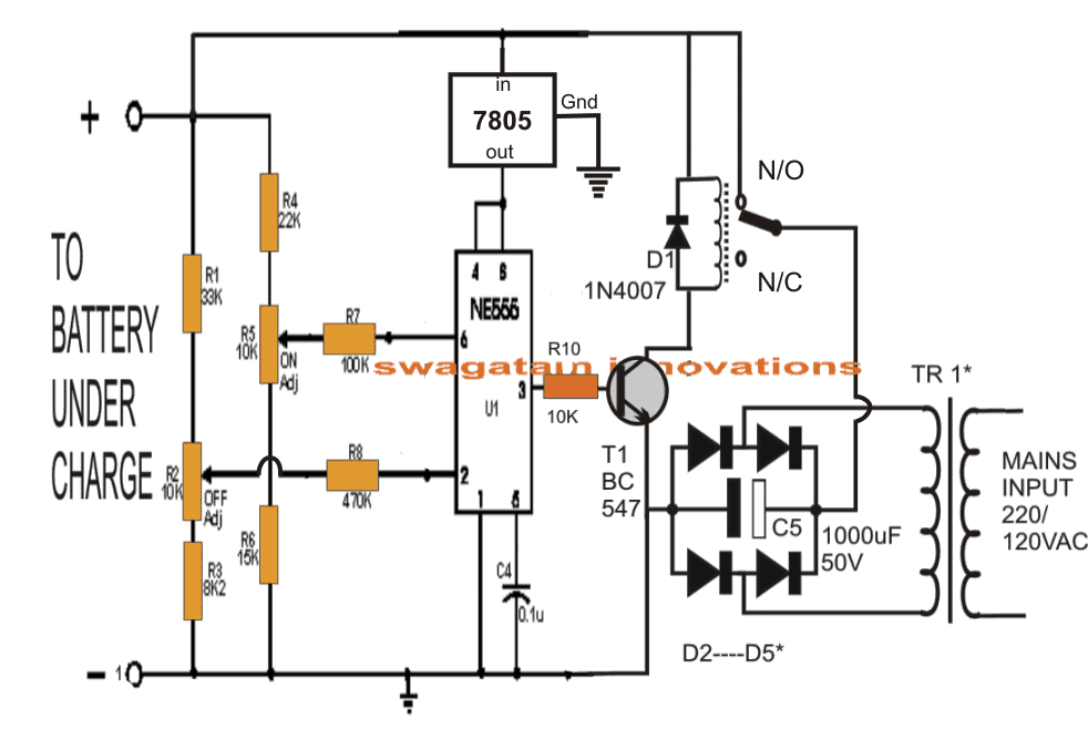
555batterychargercircuit 2, image source: www.homemade-circuits.com
Simple Inverter Circuit using CD4047, image source: www.electrosome.com

pure sine wave inverter with 555 1, image source: www.homemade-circuits.com
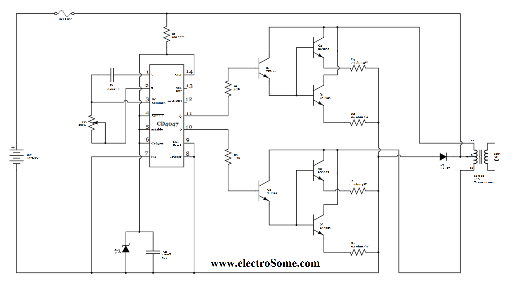
Tested Inverter Circuit Design, image source: inverter-circuit.com

rv battery disconnect switch wiring diagram on rv wiring diagram, image source: autobonches.com

Tested Inverter Circuit Design, image source: inverter-circuit.com
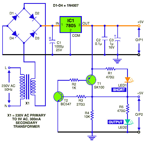
5vdc power supply circuit diagram featured short circuit protection, image source: circuitscheme.com

energy controller report schematic for operation of symbols pdf in legend and symbols single line diagram electrical house wiring pdf in legend and, image source: wiringdiagram.karaharmsphotography.com
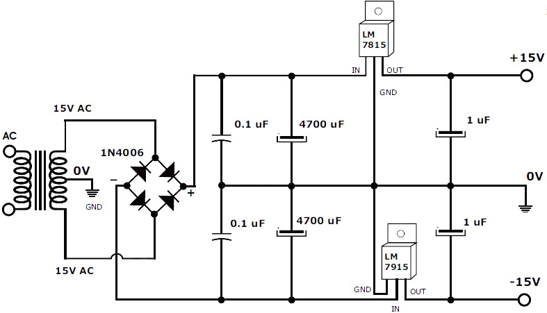
15V 1A Symmetrical Power Supply Circuit Schematic, image source: powersupply33.com
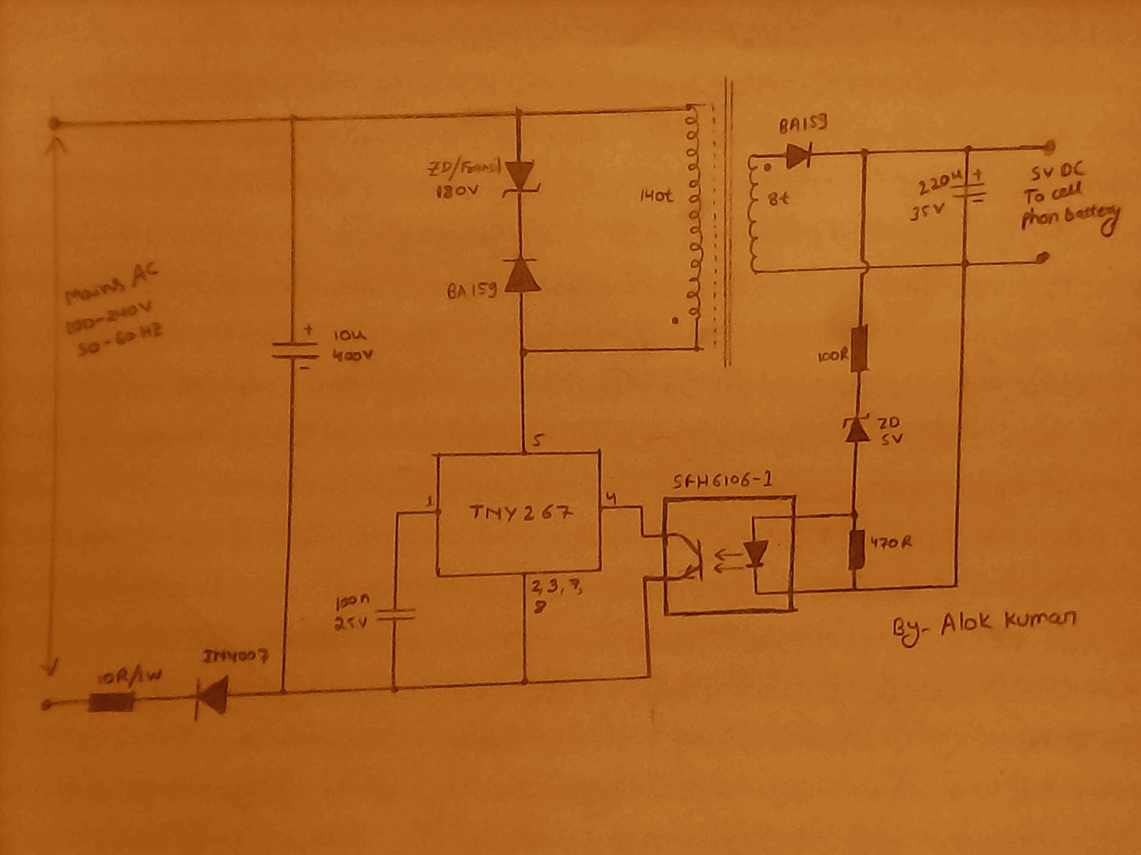
IMG_20141111_005857, image source: electronicpowersupply.blogspot.com

httpelectricaltechnology1, image source: www.electricaltechnology.org
ElecDiagram, image source: www.builditsolar.com

nintendovideoinverter, image source: www.freeinfosociety.com
24Z_Fig_1, image source: electronicsforu.com

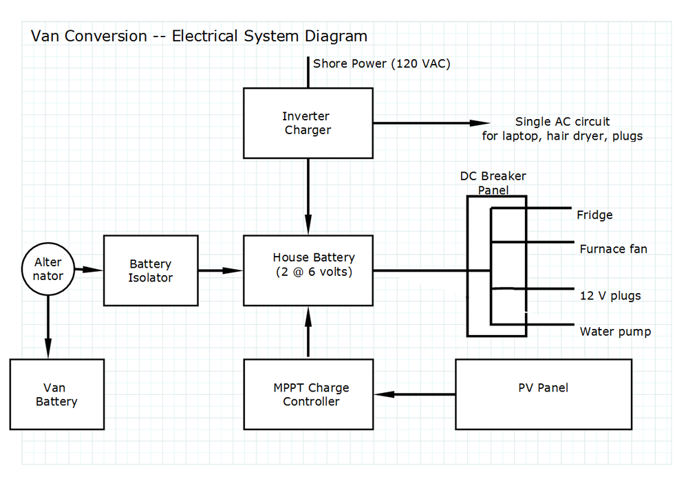
rv solar wiring diagram series parallel, image source: www.indy500.co

5_HP159_pg72_Thornton 4, image source: www.homepower.com

half bridge, image source: microcontrollerslab.com
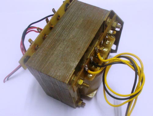
12v 0 12v step down transformer, image source: circuitdigest.com
, image source: www.survivalmonkey.com


Comments
Post a Comment